
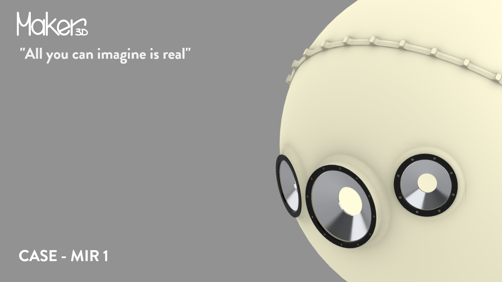
OUTLINING THE CASE
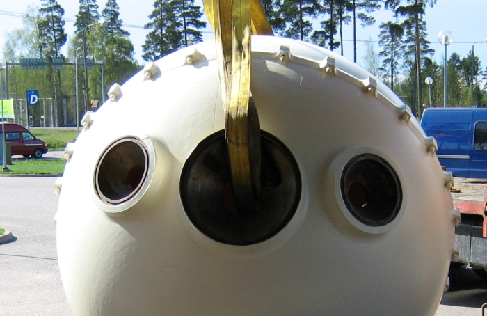
Our client wanted a model of the Mir 1 submersible’s personnel sphere to display in a museum, and we set out to create one. Having consulted with the client, we agreed to manufacture an 800mm wide model without functionality. For contrast, the original personnel sphere is 2.1 meters in diameter. Since we lacked any technical details or other measurements for the Mir 1, the only resources available were video clips provided by the client and pictures on the web.
If you’re interested in the history or other details of the Mir 1, you’ll find more information from these websites:
English: https://en.wikipedia.org/wiki/Mir_(submersible)
Finnish: https://fi.wikipedia.org/wiki/Mir_(sukellusalus)
Finnish: https://www.aamulehti.fi/a/200405064
IMPLEMENTATION
3D modelling
As agreed with the client, the model was to be 800mm in diameter, and, similarly to the original, made of two separate hemispheres. Additionally, four elements were identified that demanded great attention to detail in the designing phase, namely the collar fastening of the two hemispheres, the viewports, holes in the rear of the sphere, and the entrance hatch.
We started by modelling the two hemispheres and chose a material strong enough to withstand handling. Next, we designed the fastening mechanism of the hemispheres according to the original make-up, in which they were bolted together.
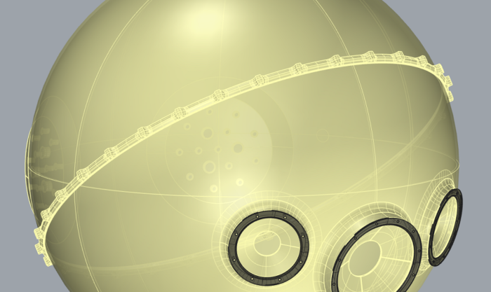
Picture 1. The collar fastener of the personnel sphere.
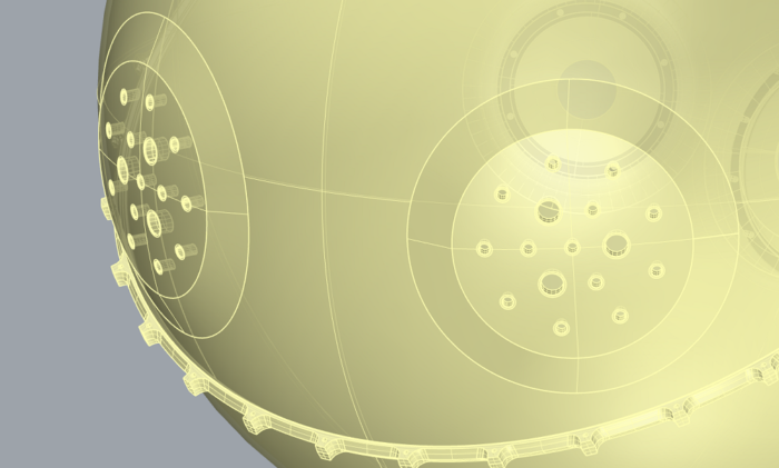
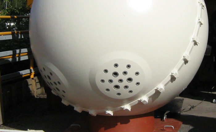
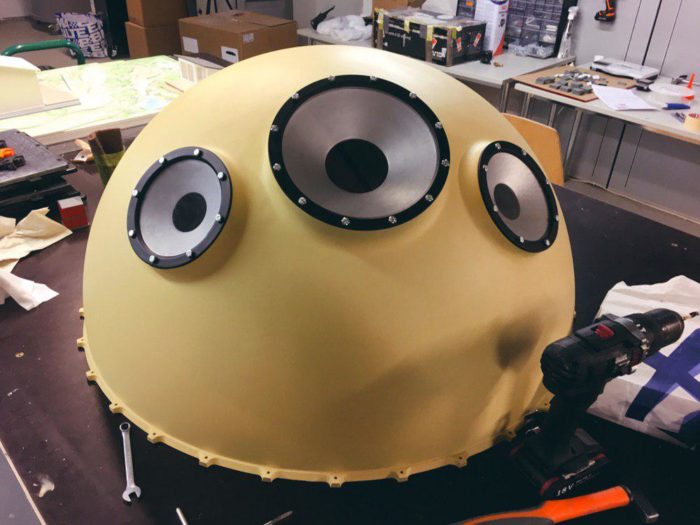
Next, the viewports on the front of the sphere, visible on the outside, were modelled. Again, we designed the viewports in the same fashion as in the original, including the collar fastener of the viewport material used to seal the viewports.
First, the diameters and locations of the viewports were sketched, then shaped the viewports as they appear in the pictures. We made the sphere thicker around the inner surroundings of the viewports to make it look thicker to the outside viewer.
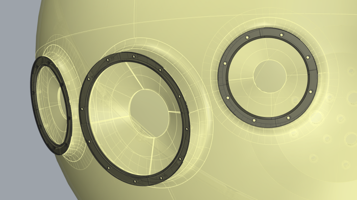
Picture 2. Viewports.
Picture 3. Collar fastener and viewports.
In the next phase, we modelled the rises in the spherical design of the other hemisphere.
Picture 4. Rises in the sphere.
Picture 5. Rises in the sphere 2.
The entrance hatch of the personnel sphere was the last modelling task. Since we had agreed with the client not to include functionality, such as hinges, modelling the hatch separately was a straightforward task. To cut printing costs, we designed the interior of the hatch as hollow, which wasn’t a problem, as the sphere was to be placed on a balcony, barring visibility to the top of the hatch.
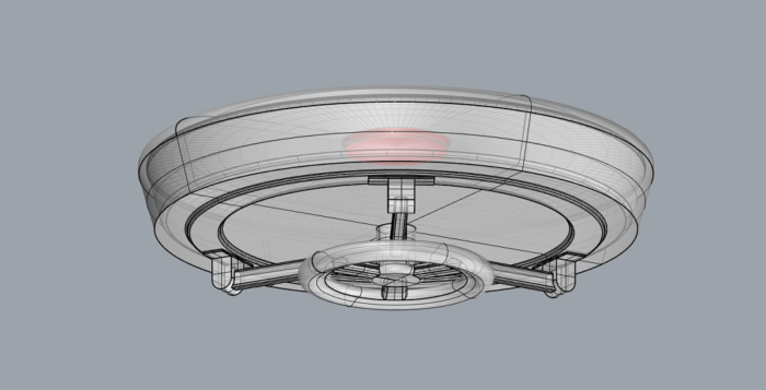
Picture 6. The entrance hatch.
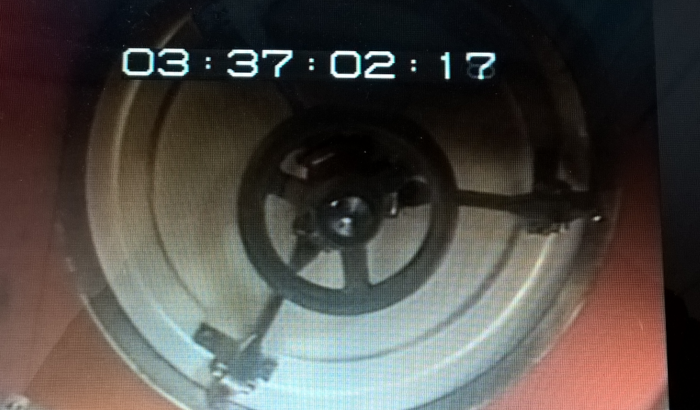
Picture 7. The entrance hatch 2.
Manufacturing Phase
The manufacturing phase comprised 3D printing several parts and gluing them together. We decided to 3D print the parts using SLA technique instead of FDM, as SLA is superior when surface quality and painting is considered. We left the hemispheres apart for easier post processing.
First, we treated the glue seams with a filler and after it had dried, sanded the seams flat. Next, the parts were treated with 2K primer and then top coated. We chose colors that best matched the tones in the coloring of the original sphere as it appears in the pictures.
We laser cut the sealing material for the viewports from acrylic and 3D printed the collar fasteners for them using FDM technique.
After post processing, the parts were bolted together, just like the original, with the exception of the entrance hatch, which was glued in place.
Picture 8. Finalized hemisphere.
The 3D printed model is on view at the ironworks museum Senkka, in Karkkila.
Finnish: https://www.karkkila.fi/ruukkimuseo/index.html
Best Regards,
Keijo Johansson
3D designing and modelling & Technical Support – Maker3D